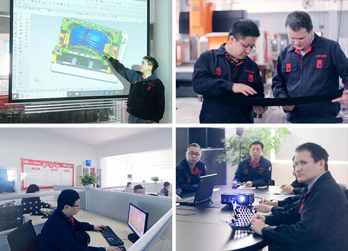
R & D MOULD engineers use modern technology design tools and technological software from world leading manufacturers, such as CAD, CAE, CAM, each of which makes it possible to carry out:
- Product sample;
- 2D drawings in electronic form (possible formats DWG; DXF, SLDDRW), or on paper carrier;
- 3D models in STEP, Parasolid, IGES or others format.


After obtaining product information, engineers proceed with the following steps:
- If there is a sample of the product, 3D-scanned, point clouds and building a 3D model of the product;
- In the presence of 2D drawings, the task is simplified and comes down to building a 3D model according to drawing.


In the mean time of develop the mold design, Designers carry out a computer analysis of the following parameters:
- checking the adequacy of the angles on surfaces of the 3D model, especially on textured and embossed surfaces;
- checking the permissible wall thickness of the product;
- determination of the sprue type, injection points and analysis of product spillage;
- determination of the mold cooling scheme and analysis of its efficiency;
- determination of possible places of accumulation of air in the cavities of the forming parts (FOD) and ensuring its release.
- analysis of filling with plastic

Together with the mold, we are ready to provide the following document:
- Mould assembly drawing
- Control schemes:electrical control circuit, hydraulic control circuit, pneumatic control circuit, kinematic control circuit, cooling system diagram and pressure test results, hot runner diagram (with catalog numbers)
- certificates for steel used in the manufacture
- hardness chart for original tooling parts
- the result of calculating "Мold Flow"